 Theta Tau | UIUC
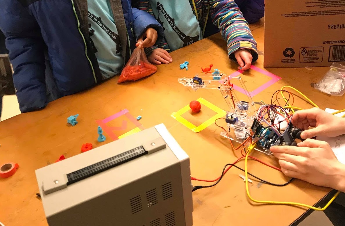
Theta Claw: An Arduino-Powered Robot Arm
Abstract
Theta Claw is a project for the 2018 University of Illinois at Urbana-Champaign Engineering Open House exhibit. It was built by our multidisciplinary team using open-source designs (with a few tweaks of our own), materials we sourced, prototyping and lab equipment available at UIUC, and some coffee-fueled late nights. We’ve documented our progress planning, assembling, and demoing the arm in this post as well as a peek at our future plans.
Theta Claw is based on MeArm, an open-source project from Mime Industries. The designs and code are available online for anyone to use and the project is intended to make robotics more accessible and affordable for everyone.
Theta Tau is a professional engineering fraternity, and our Projects committee makes a project for Engineering Open House each year. Our pasts projects include a mini tesla coil, interactive ferrofluid, and a catapult among others.
Materials
The materials needed for Theta Claw were:
- 1 Arduino Uno + breadboard
- 4 9g hobby servos
- 1 6V power supply
- 2 joystick breakout modules
- 1 3mm acrylic sheet
- Assorted fasteners (shown below)


Assembling the Arm
1) Laser Cutting Parts
We used a sheet of 3mm thick acrylic and a laser cutting machine to cut out the parts according to the drawing provided by MeArm. The laser cutter we used was the Epilog Fusion M2, available in the UIUC MechSE department’s Innovation Studio. The laser cuts the acrylic by vaporizing a thin line along each part’s outline.

2) Assembling the Pieces
We followed the MeArm V1.0 manual for steps on assembling the arm. The manual can be found here. Several pieces look very similar and without attention to detail could easily be swapped. We were able to assemble the arm with calibrated servos in place in just a couple hours during our weekly meeting. One part was warped from the laser cutting process and needed to be recut.


3) Wiring the Arm
Theta Claw is controlled using a clever system of 4 servos and the Arduino Uno microcontroller. Each servo is connected to power and a digital pin on the Arduino using jumper wires, as shown below.


4) Programming the Arduino
This is the code that we uploaded to the Arduino.
#include <Servo.h>

//define servos
Servo right;
Servo left;
Servo middle;
Servo claw;

//define joystick pins
const int R_SW_pin = 7; // Left joystick switch output connected to digital pin
const int R_X_pin = 1; // Left joystick X output connected to analog pin
const int R_Y_pin = 0; // Right joystick y output connected to analog pin

const int L_SW_pin = 6; // Left joystick switch output connected to digital pin
const int L_X_pin = 3; // Left joystick X output connected to analog pin
const int L_Y_pin = 2; // Right joystick y output connected to analog pin

//variables to store and read values from analog pins
int currRX = 0;
int currRY = 0;
int initJoyValRX = 0;
int initJoyValRY = 0;
int currLX = 0;
int currLY = 0;
int initJoyValLX = 0;
int initJoyValLY = 0;

void setup() {
  right.attach(10);
  middle.attach(11);
  left.attach(12);
  claw.attach(9);
  pinMode(L_SW_pin, INPUT);
  digitalWrite(L_SW_pin,HIGH);
  pinMode(R_SW_pin, INPUT);
  digitalWrite(R_SW_pin,HIGH);
  Serial.begin(115200);
  initJoyValLX = analogRead(L_X_pin);
  initJoyValLY = analogRead(L_Y_pin);
  initJoyValRX = analogRead(R_X_pin);
  initJoyValRY = analogRead(R_Y_pin);

  // get joystick values with no motion to remap later
  currRX = map(initJoyValRX, 0, 1023, 0, 180);
  currRY = map(initJoyValRY, 0, 1023, 0, 180);
  currLX = map(initJoyValLX, 0, 1023, 0, 180);
  currLY = map(initJoyValLY, 0, 1023, 0, 180);
}


int joyValRX_analog = 0;
int joyValRY_analog = 0;
int joyValRX = 0;
int joyValRY = 0;
int joyValLX_analog = 0;
int joyValLY_analog = 0;
int joyValLX = 0;
int joyValLY = 0;

void loop() {
  while(true){
    joyValRX_analog = analogRead(R_X_pin);
    delay(8);
    joyValRY_analog = analogRead(R_Y_pin);
    delay(8);
    joyValLX_analog = analogRead(L_X_pin);
    delay(8);
    joyValLY_analog = analogRead(L_Y_pin);
    delay(8);
    // remapping values so the initial joystick analog read is the default
    joyValRX = remap(joyValRX_analog, initJoyValRX);
    joyValRY = remap(joyValRY_analog, initJoyValRY);
    joyValLX = remap(joyValLX_analog, initJoyValLX);
    joyValLY = remap(joyValLY_analog, initJoyValLY);

    currRX += joyValRX;
    currRY += joyValRY;
    currRX = servoWrite(currRX, 90, 180); //right
    currRY = servoWrite(currRY, 0, 180); //middle

    currLX += joyValLX;
    currLY += joyValLY;
    currLX = servoWrite(currLX, 35, 70); //left
    currLY = servoWrite(currLY, 10, 145); //claw

    middle.write(currRX);
    right.write(currRY);
    left.write(currLX);
    claw.write(currLY);

    delay(20);
  }
}

int servoWrite(int curr, int minVal, int maxVal){
    if (curr > maxVal) {
      curr = maxVal;
    }
    else if (curr < minVal) {
      curr = minVal;
    }
    return curr;
}

int remap(int analog, int initJoyVal){
  int joyVal = 0;
  if (analog < 212) {
      joyVal = -1;
  }
  else if (analog > 812) {
      joyVal = 1;
  } else {
      joyVal = 0;
  }
  Serial.print(joyVal);
  return joyVal;
}

void resetServoPosition(int curr, Servo servo) {
  int new_val = 0;
  if (servo.read() < curr) {
    while (servo.read() < curr) {
      new_val = servo.read() + 3;
      servo.write(new_val);
      Serial.println(new_val);
      delay(50);
    }
  } else {
    while (servo.read() >= curr) {
      new_val = servo.read() - 3;
      servo.write(new_val);
      Serial.println(new_val);
      delay(50);
    }
  }
}
We decided on the following controls for our joysticks because they were the most intuitive - however, these could be any direction by changing a few lines of code.

5) Testing the Arduino
To power the Arduino, we used a 6V power supply.

Problems
As with any hardware project, not everything worked exactly as expected on the first try.
Position resetting:
We encountered a problem of a constant motion back to the “default” or start position of the arm. We had assumed that the signal read from the joystick for “no motion” would be directly in the middle of its min and max values; it turned out that the joystick positioned directly in the center was actually the average of the min and max offset by a value.
Servo twitching:
We also had a problem of random movement by the arm. This was due to the joystick reading random electrical signals in our circuit and interpreting those as movement input. We solved this by increasing the minimum amount the joystick needed to be pushed to trigger servo movement in the arm.
Servos locking/overheating:
The MeArm design was not perfect in that certain abrupt movements could cause the acrylic pieces to get jammed on other pieces, and the servos would continue to attempt motion despite being jammed. This would cause servos to overheat and caused us to burn out a few servos in the testing stages. We solved this problem by adding bounds to some of the servos movements (see code) to prevent motion to positions that were likely to jam the arm.
Presenting at EOH
Engineering Open House is an annual student-led event featuring two days of exhibits and competitions that showcase the work of engineering students at the University of Illinois. We had a lot of fun presenting at this event. We met many children with an interest in robotics and a few who were interested in replicating this claw at home!


Future Plans
Next up we plan to integrate computer vision with Theta Claw. Using a simple home video webcam and Aruco markers to locate objects, we plan to use YOLO, a pretrained object recognition algorithm for images, to recognize our objects and autonomously pick up a specific object. Check back soon for updates!
Projects Committee Team
Spencer Norwick , Julia Fiorino , Chris Rioux , John Ito , Aniliza May , Akhil Chainani , Mallory Wall , Victoria Nahmod